projects
Aluminum Box, Class
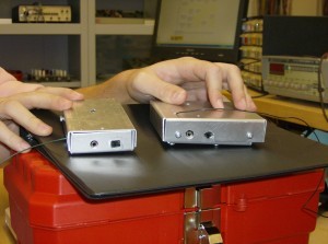
Here is a comparison of Matt’s and my aluminum enclosures for our FM Transmitters. Mines slightly bigger, and the top was a bit oversized, but I wasn’t really planning on using it anyway, I prefer to see my electronics.
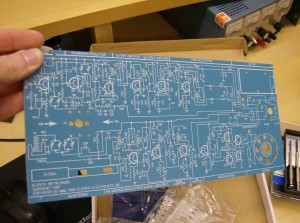
Mine is on the right. Still not bad for first try! We will be starting to build an AM/FM radio in Electronics Concepts soon, and some of the guys already got their kits. Here is the circuit board:
Its a bit big and not that practical to carry around, but its still pretty cool! Tons of components for this one. The parts are divided between the two radio sections. Perhaps as many, if not more than, the phone. Which reminds me, I should make a post showing off the phone soon. It’s pretty neat, it has a transparent case, and there are neon lights that blink when it rings!
Here we are, hard at work:
This is my seat. Notice the website I’ve got open. Also notice that YouTube is blocked…
LCD Monitor: Fixed Backlight
Well, I’ve found a solution. At work, we were going to recycle an old non-functional scanner. Before I let them take it away, I tore it open and took out the inverter for the CCFL tube inside. The rest is predictable: I took that inverter, and hooked it up to the monitor. Below is the inverter:
Technical specifications:
- Input: 9-12V (12V is of course brightest. This is the tested operating range.)
- Output: 1000V???
Pretty nifty, eh? Now, as for how I wired it up: I cut off the connectors for each of the bulbs, (though I broke one tube), and then drilled two holes in the back of the screen to let the wires come out. Now, I’m still somewhat testing whether the inverter can hold up with all three bulbs connected, or whether that will put too much strain on it. So far, with two, there are no issues, and it is more than bright enough to use.
To power the inverter, I’ve been using either a 9.6v RC car battery or the charger for that same battery, with a 12v output. The 10.8v rating was measured while the inverter was still inside the scanner, and was turned on. I tried using two 6v batteries in series, but it didn’t work, perhaps too much voltage, as I measured it to be 12.6V.
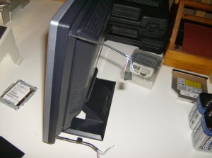
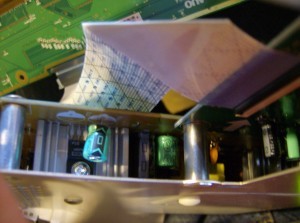
These are the wires for the backlight. I have no idea how I managed to put the whole screen back together, I forgot how it looked before, and was basically guessing how to solve the puzzle. I’ve got a few ideas for this screen, perhaps a secondary monitor, or I might even make myself a portable “rugged” PC:
Using a hard-case style wheeled-briefcase-thing, I would put in a new PC I built from used and new parts (an Athlon 64 X2 4600+ 2.4GHz with 1GB DDR2 667), and then perhaps mount the monitor somehow from the inside of the case, protect it with a sheet of acrylic-glass from the outside, and throw in some batteries and an inverter to power it on the go. Maybe…
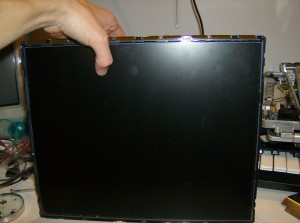
Update: Here is a picture of a semi-contained unit. It has a quick disconnect plug, and all three tubes are connected. I somewhat regret this, as, because the inverter isn’t strong enough, though I don’t believe it to be harmful, it is only able to light up all three bulbs about 3/4, so the left side of the screen is darker than the right. Still useable, but darker nonetheless. As you can see I wrapped it all in electrical tape, and I’m definitely not in the mood to tear it apart and cut one of the wires.
I think that if I just removed one of the two bottom tubes, I would be fine, with one on top, one on the bottom. It should be fairly even, though the left will still be ever so slightly darker. I also made some measurements:
Current draw:
- Two bulbs – 0.17A @ 12V
- Three bulbs – 0.11A @ 12V
Interesting… (For those who care to know: yes, the bulbs are in parallel).
LCD Monitor
Well, I recently acquired a couple of defective electronics. One of them was an LCD monitor that has a broken backlight. This kind of problem is usually caused by either a burnt bulb or a defective inverter, but regardless, it is a cause that calls upon some sort of make-ing (not spelled wrong).
Naturally, the first thing I did when I got it was tear it down, to get to the circuitry. I had remembered reading somewhere, likely Hackaday, that with one particular model of screen there was a problem with capacitors frequently overheating and drying out. I figured this would be a good place to start, though I remembered the issue with the capacitors caused a no power scenario, not a dead backlight. Regardless, I tore it open to find all the caps appeared in normal, working condition. (Funny thing, when I googled that article again, I discovered that it was actually for this exact model of screen. What a coincidence!)
I got the idea to try to use my camera flash assembly, which puts out 300v, to try and power one of the bulbs. Normally these bulbs use around/over 1000V, so my assembly was nowhere near powerful enough, so that didn’t tell me if the bulbs were dead. Then, my mom suggested to me, since I had tons of laptops with working screens, dead mobos, to try and use the bulbs from those screens. I plugged them in, and no light, on any of the two screens I tried! This tells me the inverter is to blame. Since it is part of the motherboard of the screen, it would require component replacement, and right now I’m not sure which component(s) are defective.
So, I decided, why not hack it: make my own backlight! I’ve read about this being done before on a laptop (on Hackaday, of course). He had a very old laptop, and the backlight CCFL tubes were dying. He decided to make himself an LED backlight, and though his backlight had a somewhat uneven lighting, it worked! So, I decided to dig deeper into the rabbit hole: I took apart the actual screen assembly. › Continue reading
FM Transmitter
In my Technologist as a Professional course, our Thursday period is a lab period. This means: we get to build stuff. So far, we’ve had two projects, and we have a few more on the way. The first project was to build a fully functional, variable frequency, stereo FM transmitter.
It wasn’t particularly difficult, as it came in a kit with the circuit board, components and instructions, but as it was a first project, it wasn’t meant to be difficult, either. I managed to get it working on the first try. The kit was ordered from http://canakit.com, the kit in particular is at http://www.canakit.com/hi-fi-stereo-fm-transmitter-kit-ck222b-uk222b-ck222-uk222.html.
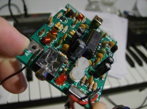
So far, as mentioned in the last post, I’ve tested the range to be roughly 2 to 2.5 houses using an MP3 player’s digital FM tuner, which naturally barely has an antennae. However, that still isn’t half bad! The two potentiometers lined up with the LED control the output volume, while the adjustable coil at the far end of the board in the picture controls the broadcast frequency. The website rates it’s frequency from 88 to 100MHz, however I can’t seem to get it much lower than 90MHz, but have no problems bringing it above 103MHz (I haven’t actually tested the whole range of it, yet, for fear of the core of the adjustable coil breaking, either coming out entirely or getting stuck down).
How is the sound quality? Depending on the frequency, varies from fuzzy to quite clear. Bass is usually a little distorted on some channels, but on the right frequency the sound comes in sharp and clear. I’m sure properly trimming the antenna for the frequency used would help, but I don’t want to optimize it permanently for just one channel, yet.
As part of our school fees, we paid for a toolbox, a bright orange plastic one that if we try hard enough we can fit the breadboard, wire strippers, screw driver kit (so far I’ve broken two of them), wire cutters, pliers, component lead-bender and box of breadboard wires that came with it. If we try slightly harder, we can also fit in our projects, hehe. I was hoping to have pictures from within the classroom, but didn’t have my camera this morning. I’ll get some for the next post, which should have my detailing of the phone I assembled!
