taap
Video Blog: Mini Amp!
Hey all, today I was given a special gift (well, I paid $24, but it was a gift nonetheless): a microphone pre-amp circuit (with mic integrated) AND a 0.5 Watt Mini Amplifier! Wow. I built both of them during class, it took about 1h30min to do both, and test. They are so awesome, the amp especially, so I made a video.
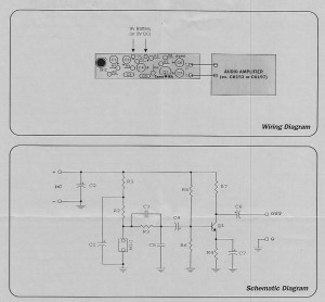
My first attempt at video blogging. Unscripted, edited to remove screw ups. Oh, technology… In any case, the mini amp is friggen’ awesome! A very simple design, aside from the IC, and the mic pre-amp is even simpler. I’m not sure if I am allowed to post this or not (if its copyrighted, let me know and I’ll take them down), but I’ve scanned the schematics in case anyone was interested in building their own. Of course, those two links are direct links to the inexpensive kits, so if you don’t feel like looking for the parts, you can order the kit with all the parts.
I was really quite impressed with how powerful the amplifier was. It is strong enough to drive my two-way, dual 6″ sub, floor-standing speakers, and create enough bass to feel in my pant legs and vibrate on my desk, equivalent to the volume I’m listening to music with my home theater amp right now. My predictions earlier at school were right: it would be equivalent to normal listening volumes. According to the equalizer display on my amp, it says about 0.1watts are going to the speakers right now. Now, I should be able to overtake any radio station with my FM transmitter!
😀
Aluminum Box, Class
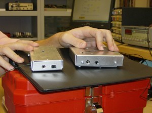
Here is a comparison of Matt’s and my aluminum enclosures for our FM Transmitters. Mines slightly bigger, and the top was a bit oversized, but I wasn’t really planning on using it anyway, I prefer to see my electronics.
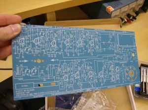
Mine is on the right. Still not bad for first try! We will be starting to build an AM/FM radio in Electronics Concepts soon, and some of the guys already got their kits. Here is the circuit board:
Its a bit big and not that practical to carry around, but its still pretty cool! Tons of components for this one. The parts are divided between the two radio sections. Perhaps as many, if not more than, the phone. Which reminds me, I should make a post showing off the phone soon. It’s pretty neat, it has a transparent case, and there are neon lights that blink when it rings!
Here we are, hard at work:
This is my seat. Notice the website I’ve got open. Also notice that YouTube is blocked…
FM Transmitter
In my Technologist as a Professional course, our Thursday period is a lab period. This means: we get to build stuff. So far, we’ve had two projects, and we have a few more on the way. The first project was to build a fully functional, variable frequency, stereo FM transmitter.
It wasn’t particularly difficult, as it came in a kit with the circuit board, components and instructions, but as it was a first project, it wasn’t meant to be difficult, either. I managed to get it working on the first try. The kit was ordered from http://canakit.com, the kit in particular is at http://www.canakit.com/hi-fi-stereo-fm-transmitter-kit-ck222b-uk222b-ck222-uk222.html.
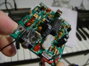
So far, as mentioned in the last post, I’ve tested the range to be roughly 2 to 2.5 houses using an MP3 player’s digital FM tuner, which naturally barely has an antennae. However, that still isn’t half bad! The two potentiometers lined up with the LED control the output volume, while the adjustable coil at the far end of the board in the picture controls the broadcast frequency. The website rates it’s frequency from 88 to 100MHz, however I can’t seem to get it much lower than 90MHz, but have no problems bringing it above 103MHz (I haven’t actually tested the whole range of it, yet, for fear of the core of the adjustable coil breaking, either coming out entirely or getting stuck down).
How is the sound quality? Depending on the frequency, varies from fuzzy to quite clear. Bass is usually a little distorted on some channels, but on the right frequency the sound comes in sharp and clear. I’m sure properly trimming the antenna for the frequency used would help, but I don’t want to optimize it permanently for just one channel, yet.
As part of our school fees, we paid for a toolbox, a bright orange plastic one that if we try hard enough we can fit the breadboard, wire strippers, screw driver kit (so far I’ve broken two of them), wire cutters, pliers, component lead-bender and box of breadboard wires that came with it. If we try slightly harder, we can also fit in our projects, hehe. I was hoping to have pictures from within the classroom, but didn’t have my camera this morning. I’ll get some for the next post, which should have my detailing of the phone I assembled!


