lcd
Final Project – Final Writeup
After yesterday’s exam, I have completed the Electronic Technologies program at Heritage College! Although final marks are not yet posted, graduation is certain, and I can pretty much call myself a Technologist (except not officially).
The biggest part of this third and final year was the final project. I’ve made a few posts in the past about it (video, menu, schematics), and the original plan was to make separate blog posts for each step of the process. However, time constraints, and the sheer volume of material, makes it easier if I just provide this summative post.
This post will be divided down into two main sections: hardware and software. I will try to explain with detail while keeping it short, and cover some of the key elements and choices involved in making this project.
When a Project Isn’t Successful
For every project I post on here where I obtain the results I was looking for, chances are there are two other projects I’ve tried that didn’t quite work out. Such is the nature of tinkering and hacking for fun.
Just because it ended in failure (and occasionally, catastrophic failure), it doesn’t mean I’ve wasted my time – here are some lessons I’ve learnt from failure over time.
LCD Monitors
Recently, my “biggest” home project has been acquiring and repairing broken LCD monitors. Most of the time, LCD monitors stop working simply due to some blown capacitors inside, and for me, this is very easy to fix. Because this is a common problem, it has been easy for me to acquire screens like this. In fact, I now have a total of 3 monitors I’ve repaired myself, along with another display that the panel was physically damaged on the top, and another monitor I couldn’t locate the capacitor causing the problem, but that I plan to convert to LED.

The display on the left is a Norcent that was destined for the trash,
the right is a Philips with a band of damage along the top.
Home Device Repair
Hello again, it has been a little bit. College has picked up, and as I am moving in a little over a week, most of my projects have been packed. However, I’ve worked on a few things in the past little while.
Remember my half-repaired LCD monitor? Well recently I obtained yet another defective LCD monitor. Symptoms: no power, no lights, no noise. I may or may not post photos about this one, because I did all repairs without taking photos, and it was a pain to take it apart, and I wish not to do so again, hehe. Basically, the cause was 4 blown caps in on the circuit board, which I’ve replaced and it now functions fully, aside from a little squealing when in stand-by or turned off (I believe due to a capacitor that started blowing but that I measured to be within proper values.)
A few months ago, however, I did document a repair project I undertook. I have two home theatre amps at home that I’ve had problems with. At one point, both had stopped functioning properly. So, naturally, I decided to set to fixing them.
LCD Monitor: Fixed Backlight
Well, I’ve found a solution. At work, we were going to recycle an old non-functional scanner. Before I let them take it away, I tore it open and took out the inverter for the CCFL tube inside. The rest is predictable: I took that inverter, and hooked it up to the monitor. Below is the inverter:
Technical specifications:
- Input: 9-12V (12V is of course brightest. This is the tested operating range.)
- Output: 1000V???
Pretty nifty, eh? Now, as for how I wired it up: I cut off the connectors for each of the bulbs, (though I broke one tube), and then drilled two holes in the back of the screen to let the wires come out. Now, I’m still somewhat testing whether the inverter can hold up with all three bulbs connected, or whether that will put too much strain on it. So far, with two, there are no issues, and it is more than bright enough to use.
To power the inverter, I’ve been using either a 9.6v RC car battery or the charger for that same battery, with a 12v output. The 10.8v rating was measured while the inverter was still inside the scanner, and was turned on. I tried using two 6v batteries in series, but it didn’t work, perhaps too much voltage, as I measured it to be 12.6V.
These are the wires for the backlight. I have no idea how I managed to put the whole screen back together, I forgot how it looked before, and was basically guessing how to solve the puzzle. I’ve got a few ideas for this screen, perhaps a secondary monitor, or I might even make myself a portable “rugged” PC:
Using a hard-case style wheeled-briefcase-thing, I would put in a new PC I built from used and new parts (an Athlon 64 X2 4600+ 2.4GHz with 1GB DDR2 667), and then perhaps mount the monitor somehow from the inside of the case, protect it with a sheet of acrylic-glass from the outside, and throw in some batteries and an inverter to power it on the go. Maybe…
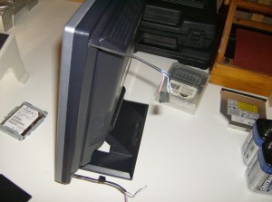
Update: Here is a picture of a semi-contained unit. It has a quick disconnect plug, and all three tubes are connected. I somewhat regret this, as, because the inverter isn’t strong enough, though I don’t believe it to be harmful, it is only able to light up all three bulbs about 3/4, so the left side of the screen is darker than the right. Still useable, but darker nonetheless. As you can see I wrapped it all in electrical tape, and I’m definitely not in the mood to tear it apart and cut one of the wires.
I think that if I just removed one of the two bottom tubes, I would be fine, with one on top, one on the bottom. It should be fairly even, though the left will still be ever so slightly darker. I also made some measurements:
Current draw:
- Two bulbs – 0.17A @ 12V
- Three bulbs – 0.11A @ 12V
Interesting… (For those who care to know: yes, the bulbs are in parallel).


