inverter
DIY: UPS
March break has found me a project! Here is a little background. My friend’s dad gave me an old Uninterruptable Power Supply (UPS) he had at home, but that the battery was no good. I have plenty of batteries, so this was a non-issue. The UPS was a godsend because that same day I had gone shopping for one, but not found one suitable for the server.

When I took this used UPS home, and hooked up all the batteries in my arsenal, I discovered that it was too weak to power the server for more than 2 seconds. Bummer. Even for power flickers that was not suitable, as there is a 5 second delay after the power returns before it switches back to mains power. What to do, what to do…
Oh, I know. Make my own!
Update: My testing proceedures blocked me from finding one critical fault with the design. As you will notice, I am using a resistor in order to short the capacitor from the AC-DC adapter, in order to more quickly de-energize the relays. Unfortunately, it still isn’t fast enough. My testing involved simply unplugging the adapter, and checking for any flickering in the devices. However, this testing does not remove mains power. Thus, the slight lag time for switch over does not affect the device, as it is has power on both relay positions. However, in a real situation, the power fails, both on input power and the adapter, and I’ve tested that my switch over time in this case is too great for most devices.
Fix to come…
LCD Monitor: Fixed Backlight
Well, I’ve found a solution. At work, we were going to recycle an old non-functional scanner. Before I let them take it away, I tore it open and took out the inverter for the CCFL tube inside. The rest is predictable: I took that inverter, and hooked it up to the monitor. Below is the inverter:
Technical specifications:
- Input: 9-12V (12V is of course brightest. This is the tested operating range.)
- Output: 1000V???
Pretty nifty, eh? Now, as for how I wired it up: I cut off the connectors for each of the bulbs, (though I broke one tube), and then drilled two holes in the back of the screen to let the wires come out. Now, I’m still somewhat testing whether the inverter can hold up with all three bulbs connected, or whether that will put too much strain on it. So far, with two, there are no issues, and it is more than bright enough to use.
To power the inverter, I’ve been using either a 9.6v RC car battery or the charger for that same battery, with a 12v output. The 10.8v rating was measured while the inverter was still inside the scanner, and was turned on. I tried using two 6v batteries in series, but it didn’t work, perhaps too much voltage, as I measured it to be 12.6V.
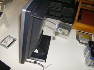
These are the wires for the backlight. I have no idea how I managed to put the whole screen back together, I forgot how it looked before, and was basically guessing how to solve the puzzle. I’ve got a few ideas for this screen, perhaps a secondary monitor, or I might even make myself a portable “rugged” PC:
Using a hard-case style wheeled-briefcase-thing, I would put in a new PC I built from used and new parts (an Athlon 64 X2 4600+ 2.4GHz with 1GB DDR2 667), and then perhaps mount the monitor somehow from the inside of the case, protect it with a sheet of acrylic-glass from the outside, and throw in some batteries and an inverter to power it on the go. Maybe…
Update: Here is a picture of a semi-contained unit. It has a quick disconnect plug, and all three tubes are connected. I somewhat regret this, as, because the inverter isn’t strong enough, though I don’t believe it to be harmful, it is only able to light up all three bulbs about 3/4, so the left side of the screen is darker than the right. Still useable, but darker nonetheless. As you can see I wrapped it all in electrical tape, and I’m definitely not in the mood to tear it apart and cut one of the wires.
I think that if I just removed one of the two bottom tubes, I would be fine, with one on top, one on the bottom. It should be fairly even, though the left will still be ever so slightly darker. I also made some measurements:
Current draw:
- Two bulbs – 0.17A @ 12V
- Three bulbs – 0.11A @ 12V
Interesting… (For those who care to know: yes, the bulbs are in parallel).


