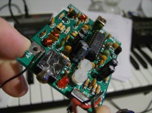
circuit board
FM Transmitter
In my Technologist as a Professional course, our Thursday period is a lab period. This means: we get to build stuff. So far, we’ve had two projects, and we have a few more on the way. The first project was to build a fully functional, variable frequency, stereo FM transmitter.
It wasn’t particularly difficult, as it came in a kit with the circuit board, components and instructions, but as it was a first project, it wasn’t meant to be difficult, either. I managed to get it working on the first try. The kit was ordered from http://canakit.com, the kit in particular is at http://www.canakit.com/hi-fi-stereo-fm-transmitter-kit-ck222b-uk222b-ck222-uk222.html.
So far, as mentioned in the last post, I’ve tested the range to be roughly 2 to 2.5 houses using an MP3 player’s digital FM tuner, which naturally barely has an antennae. However, that still isn’t half bad! The two potentiometers lined up with the LED control the output volume, while the adjustable coil at the far end of the board in the picture controls the broadcast frequency. The website rates it’s frequency from 88 to 100MHz, however I can’t seem to get it much lower than 90MHz, but have no problems bringing it above 103MHz (I haven’t actually tested the whole range of it, yet, for fear of the core of the adjustable coil breaking, either coming out entirely or getting stuck down).
How is the sound quality? Depending on the frequency, varies from fuzzy to quite clear. Bass is usually a little distorted on some channels, but on the right frequency the sound comes in sharp and clear. I’m sure properly trimming the antenna for the frequency used would help, but I don’t want to optimize it permanently for just one channel, yet.
As part of our school fees, we paid for a toolbox, a bright orange plastic one that if we try hard enough we can fit the breadboard, wire strippers, screw driver kit (so far I’ve broken two of them), wire cutters, pliers, component lead-bender and box of breadboard wires that came with it. If we try slightly harder, we can also fit in our projects, hehe. I was hoping to have pictures from within the classroom, but didn’t have my camera this morning. I’ll get some for the next post, which should have my detailing of the phone I assembled!


