Archive for November, 2009
Pinball Machine: Post #1
Well, my dad has recently become a pinball machine collector. In August, he bought his first machine, Riviera, and soon, he had acquired 4 more machines. Most recently, he acquired his first electronic pinball machine, Gorgar, by Williams, based in Chicago. Here is a brief description: released December of 1979, 14,000 units were made, it has a jungle theme to it, with a heartbeat sound in the background that speeds up as game-play intensifies. It looks to me like it will be a LOT of fun once we get it working properly.
The machine mostly works, the lights all flash, points are counted, the ball is served (one set of solenoids isn’t working right now, that bring up the GAR letter targets), however it doesn’t allow you to play more than one player (it is a four player game), and it doesn’t stop at 5 balls: you get infinite plays. › Continue reading
Mini Update: New Song
Just a small update, since getting the rock band drums working, I’ve rerecorded the whole drum track for one of my songs, and since I’m so happy about it, I’ve posted the whole song, in a higher bitrate, for all to enjoy! Go to the Music page!
Rockband Drums with Reason
The other day, I figured I should try to hook up my playstation 2 Rockband drums to my computer, to use with Reason, so that when I record my drum tracks, I can use something that actually looks similar to a drum set, instead of a keyboard. The keyboard is good for certain off-beat timed riffs, but the real drums are better for rhythm, and are more satisfying to play.
I spent plenty of time on the internet, and tried out one other method before finding this one that works the best so far. The first one I tried was something like this: Using Joy2Key, I converted the Drum Kit’s button presses to keyboard keys. Then, because Reason doesn’t support using a computer keyboard to play notes, I used another program, Live Midi Keyboard which then interpreted computer keyboard presses as not presses on an onscreen piano. Then, using MidiYokeNT, I created a virtual MIDI interface, allowing Live MIDI Keyboard to output to a virtual MIDI cable, and I set Reason to accept input from this virtual input. This worked, but with two major flaws:
- Major latency issues (too many conversion steps, keyboard repeat delay problems).
- Cannot hit two notes at the same time. Probably has to do with keyboard limitations.
Now, I have a solution that actually works, and though there still is a bit of lag, it is much better than the last setup. Unfortunately, real time playing is very difficult, requiring you to play the note before it is supposed to be heard. But, when I record music, just lowering the BPM does the trick.
The post that showed me this setup is here. It uses two pieces of software, one, MIDI Yoke NT, and another, called Rejoice. Rejoice converts the joystick signals to midi, allowing assignable notes, volumes, delays, and velocities (however, I don’t believe the program is velocity sensitive, as the controller doesn’t seem to be either).
I have it hooked up, and it makes recording music so much more fun and intuitive. Playing the music on an instrument that resembles the real thing makes coming up with a new riff a lot easier, and it requires pushing yourself to actually make it sound good. Does anyone else have a better setup, with no latency, for Windows? I found one for Mac OS X with no latency, but, that’s Mac, not PC.
Comments about Windows 7
I received a comment below from someone who installed Rejoice on his Windows 7 machine. I wrote this article while using Windows XP, but when I switched to 7 I noticed the same issue he is having – missing ocx files. You can fix this by locating the missing files, and copying them into your Program Files\Rejoice folder. I am hosting a zip with all the files here.
Video Blog: Mini Amp!
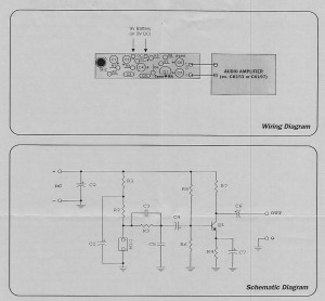
Hey all, today I was given a special gift (well, I paid $24, but it was a gift nonetheless): a microphone pre-amp circuit (with mic integrated) AND a 0.5 Watt Mini Amplifier! Wow. I built both of them during class, it took about 1h30min to do both, and test. They are so awesome, the amp especially, so I made a video.
My first attempt at video blogging. Unscripted, edited to remove screw ups. Oh, technology… In any case, the mini amp is friggen’ awesome! A very simple design, aside from the IC, and the mic pre-amp is even simpler. I’m not sure if I am allowed to post this or not (if its copyrighted, let me know and I’ll take them down), but I’ve scanned the schematics in case anyone was interested in building their own. Of course, those two links are direct links to the inexpensive kits, so if you don’t feel like looking for the parts, you can order the kit with all the parts.
I was really quite impressed with how powerful the amplifier was. It is strong enough to drive my two-way, dual 6″ sub, floor-standing speakers, and create enough bass to feel in my pant legs and vibrate on my desk, equivalent to the volume I’m listening to music with my home theater amp right now. My predictions earlier at school were right: it would be equivalent to normal listening volumes. According to the equalizer display on my amp, it says about 0.1watts are going to the speakers right now. Now, I should be able to overtake any radio station with my FM transmitter!
😀
Aluminum Box, Class
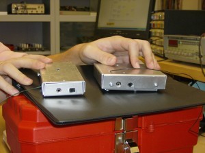
Here is a comparison of Matt’s and my aluminum enclosures for our FM Transmitters. Mines slightly bigger, and the top was a bit oversized, but I wasn’t really planning on using it anyway, I prefer to see my electronics.
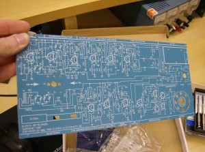
Mine is on the right. Still not bad for first try! We will be starting to build an AM/FM radio in Electronics Concepts soon, and some of the guys already got their kits. Here is the circuit board:
Its a bit big and not that practical to carry around, but its still pretty cool! Tons of components for this one. The parts are divided between the two radio sections. Perhaps as many, if not more than, the phone. Which reminds me, I should make a post showing off the phone soon. It’s pretty neat, it has a transparent case, and there are neon lights that blink when it rings!
Here we are, hard at work:
This is my seat. Notice the website I’ve got open. Also notice that YouTube is blocked…
Halloween =]
Well, this Halloween Matt suggested to me something I could do in the spirit of the occasion: setup a projector that would display creepy video: ghosts, zombies, graveyards, etc. I figured, why the heck not? The projector doesn’t get used nearly enough, so I might as well take it out for a few hours and see what happens. The video below is the result:
Pretty awesome, eh? Scary? Maybe not so much, though one kid was afraid to come up our drive way to get some candy! Not many people came by, we maybe had 8 or 10 groups of people, perhaps a total of 30 individuals. Still plenty of candy left over for me, mwuhuhuhahaha! Too much. It was neat though, how the white sheet made the perfect double sided projector screen. Sure beats paying $100+ for an actual projector screen! And of course, a white wall is still good enough (when immersed in a movie, you don’t notice things like holes and dents).
Oh, check out the Music page above, I added a new song. I’ve been working on it since June 10th, so it’s been a while I’ve been adding to it, but I listened to it again at school today and realized, damn, this is a really good song! So tonight, I added sections, created a nice piano interlude/bridge… I’m excited. In celebration, part of the song is up for you to enjoy! Again, leave me your comments!
LCD Monitor: Fixed Backlight
Well, I’ve found a solution. At work, we were going to recycle an old non-functional scanner. Before I let them take it away, I tore it open and took out the inverter for the CCFL tube inside. The rest is predictable: I took that inverter, and hooked it up to the monitor. Below is the inverter:
Technical specifications:
- Input: 9-12V (12V is of course brightest. This is the tested operating range.)
- Output: 1000V???
Pretty nifty, eh? Now, as for how I wired it up: I cut off the connectors for each of the bulbs, (though I broke one tube), and then drilled two holes in the back of the screen to let the wires come out. Now, I’m still somewhat testing whether the inverter can hold up with all three bulbs connected, or whether that will put too much strain on it. So far, with two, there are no issues, and it is more than bright enough to use.
To power the inverter, I’ve been using either a 9.6v RC car battery or the charger for that same battery, with a 12v output. The 10.8v rating was measured while the inverter was still inside the scanner, and was turned on. I tried using two 6v batteries in series, but it didn’t work, perhaps too much voltage, as I measured it to be 12.6V.
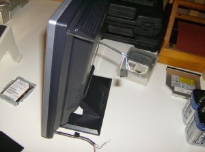
These are the wires for the backlight. I have no idea how I managed to put the whole screen back together, I forgot how it looked before, and was basically guessing how to solve the puzzle. I’ve got a few ideas for this screen, perhaps a secondary monitor, or I might even make myself a portable “rugged” PC:
Using a hard-case style wheeled-briefcase-thing, I would put in a new PC I built from used and new parts (an Athlon 64 X2 4600+ 2.4GHz with 1GB DDR2 667), and then perhaps mount the monitor somehow from the inside of the case, protect it with a sheet of acrylic-glass from the outside, and throw in some batteries and an inverter to power it on the go. Maybe…
Update: Here is a picture of a semi-contained unit. It has a quick disconnect plug, and all three tubes are connected. I somewhat regret this, as, because the inverter isn’t strong enough, though I don’t believe it to be harmful, it is only able to light up all three bulbs about 3/4, so the left side of the screen is darker than the right. Still useable, but darker nonetheless. As you can see I wrapped it all in electrical tape, and I’m definitely not in the mood to tear it apart and cut one of the wires.
I think that if I just removed one of the two bottom tubes, I would be fine, with one on top, one on the bottom. It should be fairly even, though the left will still be ever so slightly darker. I also made some measurements:
Current draw:
- Two bulbs – 0.17A @ 12V
- Three bulbs – 0.11A @ 12V
Interesting… (For those who care to know: yes, the bulbs are in parallel).
