Homebrew Stereo Gainclone Amplifier
In 2012, one of my posts were featured on Hackaday, a globally read and frequently updated aggregator of projects that modify, create, and otherwise hack. The traffic this garnered was enough to throw a couple 500 Server errors, but it also resulted in getting the attention of someone at Farnell/Newark.
I was contacted through the comments by a member of the Farnell team, who spent quite some time on my site and was “loving the content”. After further communications, he asked if I would be interested in reviewing products for them. Of course I said yes!
The question was, what would I review? After looking through some of their enormous catalog, I realized I’d rather create something out of the components I reviewed, and discovered the LM3886, a relatively inexpensive 68-watt audio amplifier. This is where the adventure began!
The Components
Here is an overview of the components used in this build, and their function. The heart of this design is the pair of LM3886 amplifiers, so I will begin with them.
LM3886
The LM3886 amplifiers have a wide operating voltage range, rated from +/- 10 to 42 VDC. A higher voltage will also result in more power handling, and more heat. There is already no shortage of heat. After less than a minute of operation, without a heatsink, even with no audio signal, they will heat up dangerously. This is expected, however, and a heatsink is a critical component in a high-power amplifier.
Sound quality is probably the most important characteristic. I have tested the amplifier with all genres of music, and found that it could easily take the place of my Technics amplifier. Bear in mind this design has almost no filtering, so electronic noise from low-quality sound cards is amplified, and there is no pop-suppression like you would find in a commercial amp.
Capacitors
I chose Panasonic capacitors for my build, including a pair of 2,200uF 50V bus caps. These guys are in place to filter the incoming positive and negative voltages, to remove any ripple which might negatively affect sound quality. Another really important purpose they serve is to handle periods of sudden current draw from the amplifier (often caused by bass).
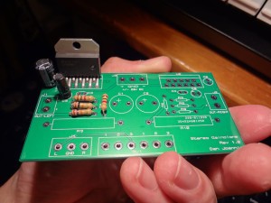
Because of this, they are large. I underestimated their size and used a foot print that was slightly too small, forcing me to be creative with their installation. I am glad I chose this higher capacity, however “Rev 2” of this design will have a larger PCB to properly accommodate the components.
The other capacitors used in this design are also Panasonic, and you may notice that they are very close to the LM3886s. This was another mistake I made. I suspect that heat will cause these capacitors to fail prematurely.
Resistors
The 10 resistors in my build are all 1/2 watt resistors. I decided on a higher power rating because I didn’t want to risk overheating any of the components.
Volume Slider
The second coolest part I ordered was a Bourns Stereo Volume Potentiometer. It is the volume control of this amplifier, and is much larger than I expected it to be. It has very smooth travel and cleanly adjusts the signal level without crackling/popping.
Schematic
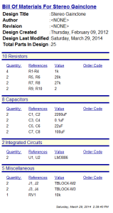
I read the datasheet for the LM3886 and wrote up a primitive parts list. A Google search led me to discover that many people were using this IC to create high-power, high-quality audio amplifiers, known as “gainclones”. I barely scratched the surface of this world, but began to get inspiration for my design.
Being my first amplifier design, I decided to not make it overly complex. I kept my circuit as simple as the reference design, but borrowed inspiration for some component values from the designs of others. In the end, my circuit has very minimal components: 6 capacitors, 8 resistors, and 2 LM3886 amplifiers.
Using the design tools provided by my college, I captured the schematic using Proteus ISIS.
PCB Layout
Once the schematic was ready, and the components were delivered, I began creating packages and laying out the circuit board. One of the design requirements I kept in mind was reducing susceptibility to noise. I did this by minimizing the length of my traces; I wanted to keep components close together. I also created a ground plane on both sides of the PCB.
As with my final project, I sent the Gerber files to iTeadstudio for manufacture. My board was 8.75cm by 4.75cm, however I’ll explain further on why I would have been better making it a little larger.
Assembly
 Once I received my PCBs (about 3-4 weeks later) I began populating a board with the components. I started by only populating the left channel and testing it, before moving on to the right side. In the event that my schematic was wrong, I didn’t want to destroy all of my components in one shot. The left and right channels are identical, with only different input and output connections.
I tested the left channel with a small speaker: success! The amplifier got quite hot, though, so after the right side was assembled and tested, I looked into a heatsink. At first I was a little ignorant to the amount of heat these amplifiers generated, and thought I could make my own. Using a piece of aluminum, I crafted a very primitive heatsink, and fastened it to the amplifiers.
It was not very effective…
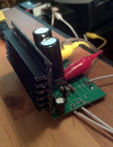
My friend Matthew offered me a heatsink he had lying around, to which I drilled new holes and sanded the back smooth, to optimize heat transfer. After confirming the metal tabs of the amplifiers were on the same net, I then secured the amplifier ICs to the heatsink, applying thermal paste in between to also improve heat transfer.
A ten minute test playing fairly bass-heavy music resulted in a generally stable temperature of around 55ºC at the face of the ICs and around 62ºC on the heatsink. Within the operation limit of 85ºC, but adding a fan greatly improved this.
Enclosure and Power Supply
July 2012
At this point, the amplifier was populated and functional, but it still needed a case and power supply. This is where the the project got shelved in July 2012.
I did purchase a box at the beginning of this project that I planned to use as an enclosure. However, I still needed a dual-polarity power supply (ie. centre-tapped transformer), and I didn’t have one on hand.
Years passed…
March 2014 – Now
In March 2014, I was contacted by a different person from Newark, who had independently discovered my website and offered me a similar invitation to the one from 2012. At this point, I had to be honest with her that I had not finished the first project, and that I would like to finish it before taking on a new one.
There were 3 problems preventing completion of this project:
- Need of a power supply
- Need of slightly better cooling
- Need of an enclosure
After some thinking and new-found motivation, I came up with the following solutions:
- Make it battery powered
- Add a fan
- Continue working with the original enclosure idea
In 2012, I didn’t have a 3D printer. Now, I do, and this allowed me to solve Problem 1 easily. Two sets of four lithium-ion batteries in series provide +/- 16V, which is on the low side, but still sufficient.
The lower operating voltages result in less heat, but I still added a video card fan to help cool things down. It runs silently on a single 18650 cell.
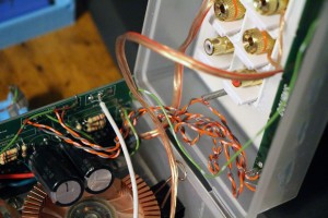
After working with the original enclosure with a rotary tool and some hot glue, all the components fit in nicely.
For power, screw terminals were added on the front, a volume knob was 3D-printed, and I ordered a keystone plate for inputs and outputs.
Final Product
It took almost 2 years for me to finish this project. It was never meant to be a high-quality, commercial product. Above all else, it was a learning opportunity where I could share the results with others and ultimately building a neat and usable device.
Total Cost
- Components from Farnell/Newark: $25
- PCBs: $25
- Keystone faceplate: $15
- 3D printed parts: $2 plastic, maybe?
- Batteries: junk pile
Total: $67
Newark Experience
The component catalog on Newark’s website is quite easy to navigate. Photo integration is quite good in the results, and shipping was very quick. I encourage you to take a look at their shop if you haven’t already.


hello sir,
for this project can i use 10k uf 25v or 50v for a 25v or 35v dual toroidal transformer?
You should always pick a capacitor voltage greater than your input voltage (see this article for basic guidelines.) For a supply of 25-35V, I would recommend using minimum 50V capacitors. If you go too low, the lifespan of the caps will be reduced significantly.