DIY: UPS
March break has found me a project! Here is a little background. My friend’s dad gave me an old Uninterruptable Power Supply (UPS) he had at home, but that the battery was no good. I have plenty of batteries, so this was a non-issue. The UPS was a godsend because that same day I had gone shopping for one, but not found one suitable for the server.

When I took this used UPS home, and hooked up all the batteries in my arsenal, I discovered that it was too weak to power the server for more than 2 seconds. Bummer. Even for power flickers that was not suitable, as there is a 5 second delay after the power returns before it switches back to mains power. What to do, what to do…
Oh, I know. Make my own!
Update: My testing proceedures blocked me from finding one critical fault with the design. As you will notice, I am using a resistor in order to short the capacitor from the AC-DC adapter, in order to more quickly de-energize the relays. Unfortunately, it still isn’t fast enough. My testing involved simply unplugging the adapter, and checking for any flickering in the devices. However, this testing does not remove mains power. Thus, the slight lag time for switch over does not affect the device, as it is has power on both relay positions. However, in a real situation, the power fails, both on input power and the adapter, and I’ve tested that my switch over time in this case is too great for most devices.
Fix to come…
Before going too far, I will of course issue a disclaimer: I am not responsible for anything you do or don’t do as a result of this post. Dealing with household electricity can be dangerous, so treat it with extreme care. A familiarity with electronics concepts is a necessity for anyone wishing to complete such a project. There are possible risks, as outlined in the risk section below, that must be understood prior to connecting anything to the finished product. I am not responsible for you breaking something (which may very well happen).
Now that that’s done, let us continue. Note: For those who do not wish to read it all, there is a video at the end of the page that will pretty much explain it all and show it in action. However, the raw information and science that follows this line is quite enthralling!
Step 1) – Design
Prior to stealing parts from the UPS, I had an initial design in mind, and though the parts I got from the UPS force me to make design 2, design 1 is the same principal and should work the same.
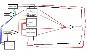
The principal behind it all is simple: When household power is supplied, the 9-12v AC-DC adapter energizes the relays, allowing household AC through and blocking the backup AC (the inverter is in standby, though turned on). When the power fails, the relays cease to be energized, and the switch positions, now blocking household AC and allowing the backup power through. When power returns, it reverts. A VERY simple design, without fancy timing circuitry, but through my testing, (spoiler warning) IT WORKS!
The only difference between design 1 and design 2 is that the relays used are different. The ones in #1 are two different types: dual independent channel normal-open and normal-closed, meaning that when no power is supplied, power goes through one, but not the other. These relays have two individual input/outputs, however both are controlled simultaniously (for the HOT and NEUTRAL wires). The relays taken from my UPS however were different: the switch doesn’t simply complete or cut a circuit: it allows you to switch between two separate inputs. Because of this, they are ideal for this situation because it allows us to rapidly switch between the two different sources instantly, keeping the HOT on one relay and the NEUTRAL on the other.
Step 2) – Parts
Because I had this other UPS lying around, I figured, best thing to do was to scavenge some parts from it.
Don’t worry if you don’t have a UPS to steal parts from: the parts I used are VERY standerdized, easy to find, and relatively inexpensive. I will offer a breakdown of the parts below, with estimated cost. I didn’t have to pay a penny for anything here because I had them already (though I may have paid for them at some point in the past.)
- 2x Bi-polar relays (where there are two selectable inputs and one output, thought it could be looked at vice-versa): ~$6 each
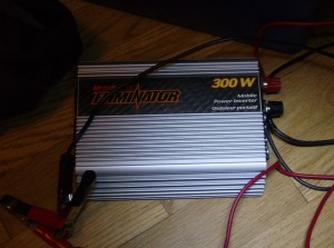
- 12v DC-AC inverter (backup power source): Depending on size, price can range from ~$20-~$300. I have a 300W and a 600W, the 300W was about $30 on sale.
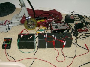
- 12v Batteries: Depending on quantity, can be anywhere from ~$30 for a smaller 7Ah battery up to… infinite. I have 6×4.5Ah batteries from three electric Razor scooters I came across, estimated value: ~$150
- 9-12V AC-DC adapter: Old cordless phones, answering machines, etc have these, ~$7
- 2x AC male connectors: I stole mine from computer power supply cables, make sure to use very flexible ones, the solid copper will break the feet on the relays, ~$5
- Resistor, ~1k Ohm, ~$0.50
- AC Receptacle: ~$2
- Switch (for battery cutoff, not necessary but for safety), make sure it can handle the amount of current needed; a 300W inverter can draw 30A@12v: ~$3-6
- Wires!!!
Step 3) – Assembly
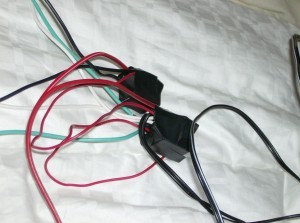
The little schematic above should be fairly self-explanatory, however here is an in-depth breakdown of the assembly steps, and the functionality. As well, a picture of the completed project, so you can better visualize the outcome.
- Grab your two relays, and set them on the table. Identify which position (pin) will be activated when there is no power: this is the connection for the backup AC. The other position is for household AC.
- One relay will be dedicated to switching the HOT wires, the other to the NEUTRAL. Choose one relay for each.
- Begin to solder the AC wiring to each relay, paying close attention to step 1. Make sure to trim the wires short enough so that you don’t have any overhang. We do not want any shorts.
- Once the INPUT AC wiring is soldered, now it is a matter of soldering the two OUTPUT wires. Solder these in place.
- Now, take your AC-DC adapter, and solder the positive and negative to one of the relays, on the pins used to activate the relay.
- Take two other wires, and solder them to these same pins on the first relay. Then, solder the other ends of these wires to the other relay.
- In parallel with the relays, anywhere coming out of the AC-DC adapter, solder a 1k Ohm resistor. This resistor will discharge the capacitor in the wallwart when power fails, allowing the relays to trigger faster.
- Now, double check all the wiring.
- Hot glue the bottoms of both relays, then wrap it all in electric tape. Don’t want to get zapped!
- Now, sort out the wires. If not yet done, put the AC male plugs on the ends of the wires for the backup and household inputs, and connect the two output wires to the AC socket. REMEMBER POLARITY! Also, tie all the grounds together.
- Triple check everything again. We are dealing with 120VAC.
- Perform a test on the relays, making sure they BOTH click when the AC-DC adapter is plugged in.
- All that remains is connecting everything! Plug the Household input, along with the AC-DC adapter, into a household plug. Plug the backup input in as well.
- Begin a small-load test run, with something cheap and low powered such as a light. Then, progressively work up to the load you desire.
The rating on your relays will tell you a maximum load. Mine say 125V @ 10A. I do not plan to pass 5A, simply because the pins on the relays are very thin, and I don’t like high current. Safety is the priority here. Now, the risk section.
RISK
Yes, this section has to exist and for good reason. This project can be dangerous to people who lack common sense, education, or understanding about the electronic concepts being treated. I can’t help the first problem, but the second two I can.
– AC voltage can stop a heart. 240V is the most dangerous, but 120V can still pack a good punch.
– Improper wiring can cause a short, leading to a fire, or if you’re lucky, just tripping a breaker. A fire is more likely.
– High loads can cause arcing on relays. Make sure your relays energize and de-energize quickly. Also, make sure to respect the relays rated maximum power, and understand that some appliances, such as pumps and motors, draw large surge currents that may surpass these ratings.
– Household AC and your backup AC will almost definitely have a phase difference. AC stands for alternating current, which basically means that the power switches between positive and negative. In North America, this happens 60 times per second. Household AC is a pure sine wave, however inverters most often put out a “modified sine wave”, which is more of a square wave. If the power fails, when switching to the backup, the phase of the household might have been at peak positive, but the inverter was at peak negative. On most devices, this is not an issue. Computers have large capacitors and a good ability to filter out noise and short-lived issues like this. Lights are unaffected. However, some sensitive equipment, or equipment with less filtered power supplies, may suffer for these differences, and may be damaged.
Testing
So far, I’ve tested my UPS with:
- 40W incandescent light
- 13W CCFL light
- 180W home theatre amplifier
- LCD Monitor
- (When I get time…) Computer
Conclusion
The project here isn’t a full UPS. I don’t tell you how to make an inverter, or a battery charger. What I tell you how to make is the circuitry that brings these different circuits together. This design is so simple it hurts. But, because it is simple it is beautiful. It works well. It is very inexpensive. It is expandable, customizable. A UPS isn’t: you are stuck with the ratings and batteries provided. With my system, changing inverters is immediate, with no downtime. Changing batteries as well. Expanding runtime is possible. And, if something stops working, you can actually fix it. If a UPS fries, you might as well throw it out. But if an individual component fails here, it can be replaced.
Hopefully this has been a solution to a problem you’ve had, and hopefully you’ve learnt some good ol’ science in the process! If you have any questions for me, leave them in the comments below, or e-mail me.
Below, a video of the UPS in action!


Okay, I may be more of a software person but that is cool.
Ok, i’m pretty sure I know how to make this work properly for you, (I had made a circuit very similar to yours) you just need a load on the wall-wart or it will will take too long for the relay to flip, I will try to post a schematic of mine later to give a better example
Ah yes, adding a load occurred to me. In my case, I put a couple 1kOhm resistors in parallel, and I found that it did make the transition slightly faster, however unfortunately it still wasn’t fast enough.
I contemplated opening the wall wart and removing the filter capacitor, hoping that the half sinewave would be able to keep the relay closed, but I never got that far. Please, I’d love to see your solution!
Is your UPS pure sine wave or modified sine wave ? does it effect in any way to the computer ??
In this design, I do not actually engineer the AC power supply – the circuitry I experimented was simply a switching circuitry, that will switch from a main supply to a backup supply in the event the main supply fails. The backup AC source can be a DC-AC inverter that is simply idle until main power fails.
To be honest this is not for me,I’ll just show this to my cousin.He does understands this more than I do,you’re actually making my brain bleed. lol..
When it comes to working with mains power (120VAC), if it hurts to think about, it will hurt more when you do it. As in deadly. There are many ways to create safety and fire risks working with this kind of electricity, so best to limit the experimentation to safe voltage levels and controlled environments.
Hi Dan.
I was trying to design some kind of “UPS” and I ended up with a design similar to yours. They are very similar actually, down to the slow de-energizing relays problem that you faced too, lol.
So I was wondering if you managed to make the transition time of the relays even sorter.
I’m working with MCUs and the time that takes for the relays to de-energize is still too much, causing the MCUs to reset (which is undesirable of course).