Adding Magnet Feature to a Bally Centaur
 Bally’s Centaur pinball machine came from the factory with an electromagnet, installed in the top-right corner of the playfield. It would hold the ball in place after it hit the “release” target, which initiates the multi-ball mode.
Unfortunately, as time passed and these electromagnets burnt out, it became more difficult and expensive to find a replacement magnet. Most games no longer have the magnet installed, as it was likely removed to be sold.
On our machine, we had no idea if the magnet was still there, and one day decided to look under the playfield to see if there was one. It turns out there was, but it didn’t work.
After verifying the electrical side was fine, we took out the magnet to find that a screw had gone through the playfield, and through the coil!


The price of a replacement electromagnet is upwards of $100! Thus, we decided we would remove the old coil wire and wrap our own. After all, how hard could it be?
General Information
A quick web search revealed that the original electromagnet had a resistance of about 51 Ohms, with some tolerance. This was our target impedance.
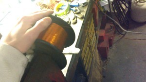
The only materials necessary to rewind the coil are magnet wire and tape. However, as we learnt, it is very important to get the correct gauge magnet wire. For this coil, you will need 27 gauge magnet wire.
Attempt #1
For our first attempt we bought 1/2 lb of 30 gauge magnet wire. This cost about $17, but as we later discovered it was the wrong gauge, so obtaining the correct resistance was difficult.
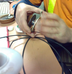
Because we were re-using the original electromagnet assembly, we more or less had to wind the coil by hand, since the mounting bracket was bent, preventing us from winding it using an automated process.
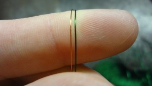
The key to winding a good electromagnet is to create even layers, and of course avoid damaging the insulation or knotting the wire. Without tools, even layers are quite difficult (read: near impossible), and so a best-effort compromise is necessary.
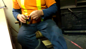
It took us approximately 1.5 hours to reach the same physical magnet size of the original, and we still had tons of wire left over.
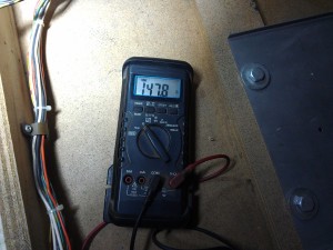
After reaching this point, we measured the resistance of the coil:
Uh oh. That is almost 100 Ohms more than the original 51 Ohm value, but the size is the same. We installed it anyway, and found that it was too weak.
This is when we realized that the gauge is very important. Because our 30 gauge wire was thinner than the required 27 gauge, it took more wire to fill the coil, and the final resistance was much higher. To bring the resistance down to 51 Ohms, we had to unwind almost two-thirds of the wiring, and by that point, the area of the magnet was too small and ineffective.
Attempt #2
Armed with new knowledge, we purchased an enormous roll of the correct, 27 gauge wire. It cost us $40, and so far has allowed us to wind 2 electromagnets.

This time, instead of re-using the original mount and bracket, we built our own.
 The base was modelled after the original, and for the metal core we cut a bolt.
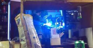
The bolt was fixed in place with a MIG welder, with a washer welded to the end of the bolt to act as a wire-stop. As well, a short piece of metal rod was welded to the end of the bolt, so that we could wind the coil much quicker.
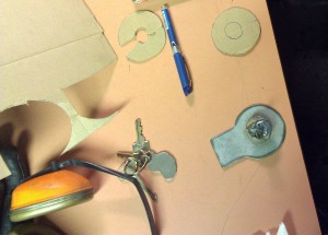
Little pieces of cardboard were cut to act as insulators, and were taped in place. Any metal parts that the wires might touch were covered in liquid electrical tape before winding.
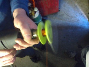
Finally, the rod was tightened into the drill, and powered winding began! Instead of taking 1h30 to wind, it took about 5 minutes. And it worked much better.
Once the electromagnet was fully wired, we taped the coil in place, and ground off the metal rod.
We tested the resistance of our first coil, and found it to be 38 Ohms. Much better than 150 Ohms, but it also means it will put slightly more strain on the electronics. However, for the number of times you will actually manage to activate the magnet, I’m not too concerned.
We made a second coil following the same process, and reached 43 Ohms. I believe that our model is slightly smaller than the original, so we cannot fit as much wire around it.





Interesting read guys and thanks for posting. My Gorgar magnet has just suddenly packed up.I’m a bit of a novice,can you offer any advice which process i should follow to determine if i need a recoil? I’m not even sure which fuse at what size goes where?
Any advice you could offer i much appreciated.
Kind Regards
Scott
Hey Scott, unfortunately my Gorgar is being stored at a friend’s house some 2300km away, so I can only give you general recommendations without specific values. Before I get super into detail and possibly overwhelm you – check the simple things first. Make sure the switch for the magnet is good. Do the lights flash and does Gorgar say “Me Hurt” when you hit it?
Here is more detail:
1) As you indicated, the first place to check is the fuse. Even if you don’t know which one it is, check all of them. There should never be a blown fuse on a properly functioning game. Unless it was removed, there should be a paper indicated the fuses and their values, found inside the back box or in the cabinet. Chances are though, if the fuse is blown, many other solenoids/lights are also not working.
2) There are a few ways this could go.
a) If the fuse is blown, you change it, and it blows again, you possibly have a short at the playfield (such as a shorted coil or wiring), or a driver transistor has failed. This involves investigating anything that fuse provides power to, and looking for obvious damage. Transistors can blow visibly, but often the only way to test them is with a multimeter on the “diode test mode”. Then, you can check that none of the pins on a single transistor are short.
b) If the fuse is not blown, and the coil is the only thing not working, it could be isolated to the coil.
b1) First check that there is voltage across the coil when it is powered. You’ll need the game on for this, so be very careful with all testing tools to not cause new damage. If there is no voltage at the coil, it could be a bad magnet relay, or again maybe the switch triggering the relay is dirty or poorly adjusted.
b2) Check the resistance across the coil. The nominal value should be something above 30 and below 200 Ohms (really ball-parking it, I can’t remember for this game). The reality is, if there is a failure, the value will be an extreme: 0 ohms (shorted), or infinity ohms (open). You may need to remove the coil from the circuit to get an accurate reading.
At this point, if you are getting power to the coil but the resistance is bad, you will need to recoil.
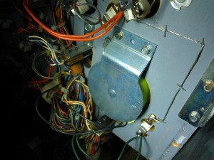
Here is a clip of the playfield wiring diagram, which indicates the wiring path for the magnet. The entire schematic document is 73mb, and can be found here.
Hi Dan
I have just fixed the magnet function on my Centaur (didn’t even know it had one till i saw it on a youtube !)
But once i fixed it, i didnt know what i had to do in game play to activate it!
Your blog has solved that mystery, thank you very much.
I admire you commitment to the repair.
regards Grant
Hi Grant,
Thank you for the reply. I’m happy you could find that information, of all things, from my post. It is a tricky shot, but certainly worthwhile if you’ve collected all your gorgons!
Dan