Final Project – Final Writeup
After yesterday’s exam, I have completed the Electronic Technologies program at Heritage College! Although final marks are not yet posted, graduation is certain, and I can pretty much call myself a Technologist (except not officially).
The biggest part of this third and final year was the final project. I’ve made a few posts in the past about it (video, menu, schematics), and the original plan was to make separate blog posts for each step of the process. However, time constraints, and the sheer volume of material, makes it easier if I just provide this summative post.
This post will be divided down into two main sections: hardware and software. I will try to explain with detail while keeping it short, and cover some of the key elements and choices involved in making this project.
Hardware
I’ve always felt like a hardware guy at heart. I love building, testing, repairing devices at the electrical level. The analog world has a kind of magic to it, where it isn’t always consistent, and there is an element of uncertainty and deviance to it. This really showed while working on my final project.
Microcontroller
I use the term microcontroller, as microprocessor simply doesn’t do justice to the functionality offered by the ATMega series. I chose the cream of the crop in through-hole micros: the ATMega1284p. This chip is a monster: 16k SRAM, 128k Flash, two uarts, 8 Analog-Digital Conversion pins. I didn’t want to limit my code with the hardware, and spared no expense: the chip cost $6.
I am running the micro at its maximum frequency of 20MHz, at 5V.
Temperature Sensor
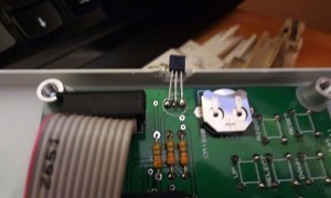
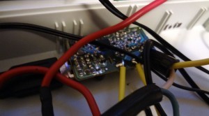
As mentioned before, the sensor I chose was the TMP36. I picked it because of how simple it is to use: two power pins, and one output. That’s it. However, in practice this sensor is very difficult to use on a breadboard, and seems either prone to noise or losses, though on the PCB it performs flawlessly.
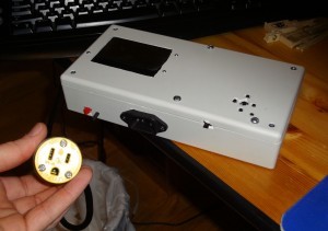
Because the sensor needs to measure the room temperature, I carved a groove in the project box so that it measures room temperature, not box temperature.
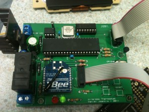
After I had my PCB made, I noticed I made a small mistake: I had connected the Analog-Digital Converter reference voltage to 5V on the microcontroller. The maximum output voltage of the TMP36 is under 2V, so my measurements have much less resolution – approximately 0.5*C. In my revised design, the AREF is set to 3.3V, giving me perhaps 0.2*C resolution.
LCD Display
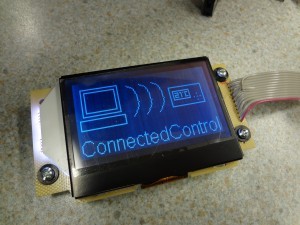
I used the ST7565 Negative Graphic LCD from Adafruit. Although in the end it looks pretty cool, there a couple things that made this a less simple to use peripheral.
Library
The Adafruit provided library was very bloated. Data was bit-banged over SPI, and she included too much extraneous debugging code, that sent out uart data anytime anything happened on the display. As well, she included a lot of demo display code which bloated the library.
I cleaned out her library, removing all the unnecessary functions and conversion utilities, and set it up to use the SPI functionality of the AVR. My library files are included at the end of this post.
XBee
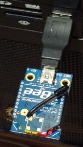
For the wireless communication aspect, I used a pair of XBees, which are little Radio Frequency devices that transmit and receive serial data. One is connected by USB to the computer, and the other is mounted on the thermostat’s PCB.
These were very easy to use. It is pretty much plug and play, but because some of my classmates were also using XBees, out of the box they were all communicating together. To solve this, we all configured our XBees using the X-CTU software such that they would only talk to their other pair.
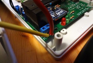
The only issue I have with the XBee is due to how I placed it on the PCB. The relay is right beside the XBee. When the relay triggers, the electromagnetic pulse generates garbage data on the TX line, causing the XBee to transmit a couple bytes of garbage. The way my communication protocol is designed, this data doesn’t represent any commands so it gets ignored.
Real Time Clock (RTC)
Because a programmable thermostat relies on the time in order to determine where it is in the schedule, I needed to include an RTC. Although several of my classmates simply used a 32.768kHz crystal with their ATMegas, and simply made their micro responsible for keeping track of time, this simply isn’t an option for me. When power is lost, the time is reset on their projects. For a thermostat this means complete system failure. So, I chose an RTC with battery backup.
I am using the DS1307, a Real Time Clock that communicates over i2c. It compensates for leap years and will keep accurate time until 2100. It has a pin that connects to a 3V watch battery, allowing it to keep time even when not powered.
When incorporating this into my design, I simply copied the schematic provided with the DS1307 kit I purchased from Adafruit. I bought her kit simply for the parts; the PCB was unnecessary.
Packaging
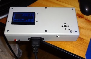
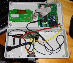
Everything was wrapped together by mounting the hardware inside a project box. This finalization stage is what actually took the project from a theoretical thermostat to a functional one. In this stage I added the electrical input and output to provide 120VAC to a heating/cooling device.
The main PCB and the LCD are both mounted on the lid of the project box. I made some changes to the PCB at this stage with regards to the power supply. Before, it would accept input from 7-30VDC, and the 7805 5V regulator would regulate 5V for the project. However, I had an old cellphone charger available, and it had an output of 5V. Because the charger was so compact, it made sense to use this as my power supply, and I had to remove the voltage regulator from my PCB.
I jumpered the input and output pins where the voltage regulator used to be, and I removed and jumpered the input protection diode, because it caused the voltage to drop too much. This way, I could connect one end of the power cable to the terminal block, and the other end was a USB male end, plugged into the cellphone charger. The cellphone charger takes its power directly from the 120VAC input.
For safety, I included a 15A breaker in the project, to protect in the event of a short circuit. I tried to use the highest guage possible of wire for AC. The only point I am worried about over long term is the terminal block on the PCB, where the AC goes to the relay. It seems that time and stress may make it possible for one of the AC wires to slip out, which could be very bad. I will keep and eye on this.
For the voltage input, a Computer Modular Cable socket was used, taken from a defective power supply. This makes it very easy to find a cable to plug it all in. The load (heater) is plugged into a socket at the end of a 1.5′ cable. Ideally I would have liked a socket mounted in the project box, but time was running out and it would be difficult to locate one that fit just right.
Software
That’s it for the hardware, now it is time for the software. This is a bit less easy to show off. There are over 2,500 lines of code, found in 17 library files and 1 main file. Compiled it uses around 2k of SRAM and 40k of Flash.
Main
The main C file contains initialisation calls, the menu systems, and the main loop. Let me go over the two most interesting parts.
Menu
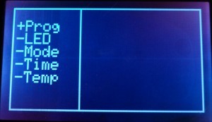
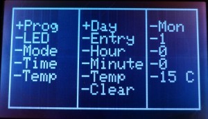
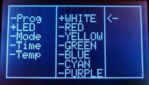
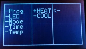
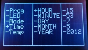
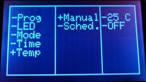
The menu system was probably the most complex thing to work with for the entire software aspect. It involved creating a unified theme for the menus, having intuitive interaction with the buttons, and including all the functionality to make this a standalone device. It was important to me that everything you could do with the Windows software was also possible right from the device.
There are 5 menu items:
Main Menu
Schedule Programming Menu
LED Menu
Operation Mode Menu
Set Time Menu
Temperature Mode Menu (Including Override Option)
In software, this involved drawing line objects as delimiters for each menu box, and drawing text string on the display. I used the “+” to indicate the currently selected menu item, although I discovered much later there is an arrow character.
The code for the menu is disgusting: it is simply so large and layered. It makes use of so many if/else statements and so many variables to keep track of where you are in the menu. It began using a system of x and y coordinates, however this did not work as the menus were not all equal in size, so new variables had to be created for each primary menu item.
Main Loop
This while loop is what contains the functionality of the thermostat. It will check the current time. It will then check the schedule, and see whether the time matches any schedule entries.If it is in scheduled operation mode, it will set the current target temperature to the schedule target temperature. It will check for any uart instructions, and execute them as needed, and will check the current temperature. Based on the operating mode, it will determine whether or not the relay needs to be on or off.
if(temperature < 10*(target_temp – 1)){
PORTA |= (1 << 6);
relay_enabled = 1;
}
else if(temperature > 10*(target_temp + 1)){
PORTA &= ~(1 << 6);
relay_enabled = 0;
}
The target temperature is acquired at +/- 1*C. For example, in heating mode, if the target is 22*C, the relay will keep the heater on until it reaches 23*C, at which point it will turn it off. It will keep it off until the current temperature is 21*C, at which point the cycle will restart. This is partly because it makes no sense to have the relay toggling every 20 seconds, and also due to the limited resolution. The hardware revision now allows for 0.2*C resolution, which could provide more precise temperature control.
EEPROM
Settings such as backlight colour, operating mode, and of course the schedule, are all stored inside the EEPROM. This means that, when the device is turned off and on, these settings aren’t lost, and it will resume normal operation without assistance. The most complicated part about this was storing my schedule structure in EEPROM. The schedule will be described in more detail below, but it is a structure within a structure within a structure. Looking online for inspiration, I modified a bit of code that use a clever trick:
void WriteStructureToEeprom(struct sched_week a){
eeprom_write_block((const void*)&a, (void*)25, sizeof(struct sched_week));
}
The eeprom_write_block() function takes three arguments: the address in RAM of that which is to be copied, the EEPROM address to which it should be written, and the size of the block of data to be written. By using the sizeof() function to return the size of the schedule structure, I am certain to store the structure in its entirety.
Scheduling
The scheduling is really the biggest part of this project. It is what makes this comparable to modern programmable thermostats, but also allows me to do better than them.
Because scheduling is based on the day of the week, I needed to determine the day of the week from the current date. I picked a reference date of Janurary 1st, 2012, because it fell on the first day of the week (Sunday). 2012 is also a leap-year, making it an even better reference date. To determine if the current year is a leap-year, I simply check if it is a multiple of 4 after 2012. Then, I simply determine the Julian date (the day of the year, x/365), and divide by 7 to find the remainder, which corresponds to the day of the week.
weekday = (julian_date % 7);
Structure
The schedule is stored in a structure of structures. The is a structure for each entry, each day, and each week.
struct sched_entry{
unsigned char hour;
unsigned char minute;
signed char target_temperature;
};
struct sched_day{
struct sched_entry entry0;
struct sched_entry entry1;
struct sched_entry entry2;
struct sched_entry entry3;
struct sched_entry entry4;
};
struct sched_week{
struct sched_day sunday;
struct sched_day monday;
struct sched_day tuesday;
struct sched_day wednesday;
struct sched_day thursday;
struct sched_day friday;
struct sched_day saturday;
};
Conclusion
There is so much more to this project, as with all projects. The source code is so large I doubt anyone except someone who wanted a ready made device identical to this would go through it, but I will provide my source code openly. I will also provide my modified LCD libraries separately, released of course respecting Adafruit’s existing license.
